郭德纲单口相声下载,魔兽世界幻化法杖,绍兴租房网


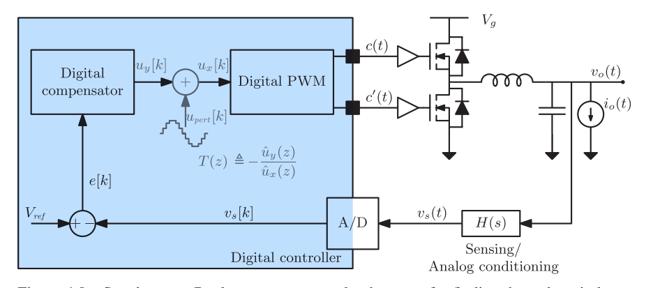
本书系统分析了高频开关电源的设计分析、建模和数字控制技术,包括
功率开关电源数字闭环控制原理的理解
开关电源建模推导
电压环数字控制,电流环数字控制
双环控制技术的分析与设计
PID设计
PID算法的Verilog和VHDL代码
开关电源的设计和建模
开关电源闭环补偿网络设计
开关电源的FPGA数字控制设计
FPGA的Verilog代码实现
PREFACE ix
INTRODUCTION 1
CHAPTER 1 CONTINUOUS-TIME AVERAGED MODELING OF DC–DC CONVERTERS 13
1.1 Pulse Width Modulated Converters 14
1.2 Converters in Steady State 16
1.2.1 Boost Converter Example 17
1.2.2 Estimation of the Switching Ripple 19
1.2.3 Voltage Conversion Ratios of Basic Converters 20
1.3 Converter Dynamics and Control 21
1.3.1 Converter Averaging and Linearization 22
1.3.2 Modeling of the Pulse Width Modulator 24
1.3.3 The System Loop Gain 25
1.3.4 Averaged Small-Signal Models of Basic Converters 26
1.4 State-Space Averaging 28
1.4.1 Converter Steady-State Operating Point 28
1.4.2 Averaged Small-Signal State-Space Model 29
1.4.3 Boost Converter Example 30
1.5 Design Examples 32
1.5.1 Voltage-Mode Control of a Synchronous Buck Converter 32
1.5.2 Average Current-Mode Control of a Boost Converter 42
1.6 Duty Ratio d[k] Versus d(t) 48
1.7 Summary of Key Points 50
CHAPTER 2 THE DIGITAL CONTROL LOOP 51
2.1 Case Study: Digital Voltage-Mode Control 52
2.2 A/D Conversion 53
2.2.1 Sampling Rate 53
2.2.2 Amplitude Quantization 56
2.3 The Digital Compensator 58
2.4 Digital Pulse Width Modulation 63
2.5 Loop Delays 65
2.5.1 Control Delays 65
2.5.2 Modulation Delay 66
2.5.3 Total Loop Delay 70
2.6 Use of Averaged Models in Digital Control Design 71
2.6.1 Limitations of Averaged Modeling 71
2.6.2 Averaged Modeling of a Digitally Controlled Converter 74
2.7 Summary of Key Points 78
CHAPTER 3 DISCRETE-TIME MODELING 79
3.1 Discrete-Time Small-Signal Modeling 80
3.1.1 A Preliminary Example: A Switched Inductor 82
3.1.2 The General Case 85
3.1.3 Discrete-Time Models for Basic Types of PWM Modulation 87
3.2 Discrete-Time Modeling Examples 88
3.2.1 Synchronous Buck Converter 90
3.2.2 Boost Converter 97
3.3 Discrete-Time Modeling of Time-Invariant Topologies 102
3.3.1 Equivalence to Discrete-Time Modeling 106
3.3.2 Relationship with the Modified Z-Transform 108
3.3.3 Calculation of Tu(z) 108
3.3.4 Buck Converter Example Revisited 112
3.4 Matlab® Discrete-Time Modeling of Basic Converters 112
3.5 Summary of Key Points 117
CHAPTER 4 DIGITAL CONTROL 119
4.1 System-Level Compensator Design 119
4.1.1 Direct-Digital Design Using the Bilinear Transform Method 120
4.1.2 Digital PID Compensators in the z- and the p-Domains 123
4.2 Design Examples 126
4.2.1 Digital Voltage-Mode Control of a Synchronous Buck Converter 126
4.2.2 Digital Current-Mode Control of a Boost Converter 134
4.2.3 Multiloop Control of a Synchronous Buck Converter 136
4.2.4 Boost Power Factor Corrector 141
4.3 Other Converter Transfer Functions 154
4.4 Actuator Saturation and Integral Anti-Windup Provisions 160
4.5 Summary of Key Points 165
CHAPTER 5 AMPLITUDE QUANTIZATION 167
5.1 System Quantizations 167
5.1.1 A/D Converter 167
5.1.2 DPWM Quantization 169
5.2 Steady-State Solution 172
5.3 No-Limit-Cycling Conditions 175
5.3.1 DPWM versus A/D Resolution 175
5.3.2 Integral Gain 178
5.3.3 Dynamic Quantization Effects 181
5.4 DPWM and A/D Implementation Techniques 182
5.4.1 DPWM Hardware Implementation Techniques 182
5.4.2 Effective DPWM Resolution Improvements via ΣΔ Modulation 186
5.4.3 A/D Converters 187
5.5 Summary of Key Points 190
CHAPTER 6 COMPENSATOR IMPLEMENTATION 191
6.1 PID Compensator Realizations 194
6.2 Coefficient Scaling and Quantization 197
6.2.1 Coefficients Scaling 198
6.2.2 Coefficients Quantization 200
6.3 Voltage-Mode Control Example: Coefficients Quantization 203
6.3.1 Parallel Structure 204
6.3.2 Direct Structure 206
6.3.3 Cascade Structure 208
6.4 Fixed-Point Controller Implementation 213
6.4.1 Effective Dynamic Range and Hardware Dynamic Range 214
6.4.2 Upper Bound of a Signal and the L1-Norm 216
6.5 Voltage-Mode Converter Example: Fixed-Point Implementation 218
6.5.1 Parallel Realization 220
6.5.2 Direct Realization 225
6.5.3 Cascade Realization 229
6.5.4 Linear versus Quantized System Response 233
6.6 HDL Implementation of the Controller 234
6.6.1 VHDL Example 235
6.6.2 Verilog Example 237
6.7 Summary of Key Points 239
CHAPTER 7 DIGITAL AUTOTUNING 241
7.1 Introduction to Digital Autotuning 242
7.2 Programmable PID Structures 243
7.3 Autotuning VIA Injection of a Digital Perturbation 247
7.3.1 Theory of Operation 249
7.3.2 Implementation of a PD Autotuner 253
7.3.3 Simulation Example 255
7.3.4 Small-Signal Analysis of the PD Autotuning Loop 261
7.4 Digital Autotuning Based on Relay Feedback 265
7.4.1 Theory of Operation 266
7.4.2 Implementation of a Digital Relay Feedback Autotuner 267
7.4.3 Simulation Example 271
7.5 Implementation Issues 272
7.6 Summary of Key Points 275
APPENDIX A DISCRETE-TIME LINEAR SYSTEMS AND THE Z-TRANSFORM 277
A.1 Difference Equations 277
A.1.1 Forced Response 278
A.1.2 Free Response 279
A.1.3 Impulse Response and System Modes 281
A.1.4 Asymptotic Behavior of the Modes 282
A.1.5 Further Examples 283
A.2 Z-Transform 284
A.2.1 Definition 284
A.2.2 Properties 285
A.3 The Transfer Function 287
A.3.1 Stability 287
A.3.2 Frequency Response 288
A.4 State-Space Representation 288
APPENDIX B FIXED-POINT ARITHMETIC AND HDL CODING 291
B.1 Rounding Operation and Round-Off Error 291
B.2 Floating-Point versus Fixed-Point Arithmetic Systems 293
B.3 Binary Two’s Complement (B2C) Fixed-Point Representation 294
B.4 Signal Notation 296
B.5 Manipulation of B2C Quantities and HDL Examples 297
B.5.1 Sign Extension 298
B.5.2 Alignment 299
B.5.3 Sign Reversal 301
B.5.4 LSB and MSB Truncation 302
B.5.5 Addition and Subtraction 304
B.5.6 Multiplication 305
B.5.7 Overflow Detection and Saturated Arithmetic 307
APPENDIX C SMALL-SIGNAL PHASE LAG OF UNIFORMLY SAMPLED PULSE WIDTH MODULATORS 313
C.1 Trailing-Edge Modulators 313
C.2 Leading-Edge Modulators 317
C.3 Symmetrical Modulators 318
REFERENCES 321
INDEX 335
=====================================================================================================================================
下载高清PDF文档地址:
 或
或
=====================================================================================================================================
如对本文有疑问,请在下面进行留言讨论,广大热心网友会与你互动!! 点击进行留言回复
Blazor server side 自家的一些开源的, 实用型项目的进度之 CEF客户端
.NET IoC模式依赖反转(DIP)、控制反转(Ioc)、依赖注入(DI)


vue+.netcore可支持业务代码扩展的开发框架 VOL.Vue 2.0版本发布

网友评论